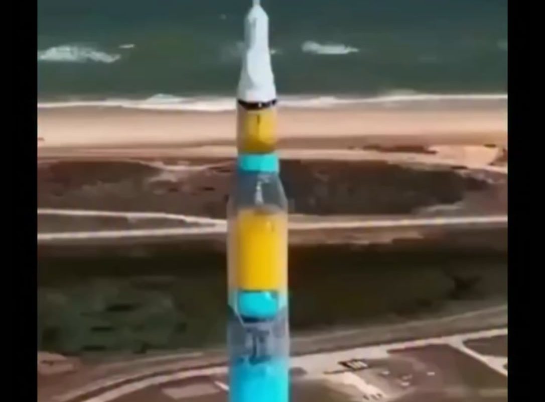
Visualization of a rocket’s fuel system.!!
Meta Description: Explore the intricate world of rocket fuel systems through visualization. Discover how engineers design, monitor, and optimize fuel flow for space missions, featuring 3D models, animations, and VR tools.
Visualizing a Rocket’s Fuel System: Engineering the Lifeline of Space Travel
Rockets are feats of engineering precision, and at their core lies a critical component: the fuel system. This complex network of tanks, pumps, valves, and pipelines delivers propellant to engines at extreme speeds and pressures. Visualizing these systems is key to understanding how rockets work, optimizing their design, and training engineers for real-world scenarios. Here’s how we bring rocket fuel systems to life through technology.
Why Visualization Matters
Rocket fuel systems operate under brutal conditions—cryogenic temperatures, rapid pressure shifts, and microgravity—making physical testing expensive and risky. Visualization lets engineers:
- Identify flaws in design before manufacturing.
- Simulate fluid dynamics to predict fuel behavior.
- Train teams on emergency protocols using virtual models.
Without visualization, innovation in rocketry would stall.
Anatomy of a Rocket Fuel System: Key Components
Visualization breaks down the system’s complexity:
1. Propellant Tanks
- Liquid Fuel (RP-1, LH2) and Oxidizer (LOX) stored in insulated tanks.
- Visual Insight: 3D cross-sections showing tank geometries, baffles (to prevent sloshing), and temperature gradients.
2. Turbo pumps & Feed Lines
- Ultra-high-speed pumps move fuel at 1,000+ gallons per second.
- Visual Insight: Animated flow simulations reveal pressure drops or cavitation risks.
3. Combustion Chamber & Injectors
- Fuel mixes explosively with oxidizer via injector plates.
- Visual Insight: CFD (Computational Fluid Dynamics) models show spray patterns and combustion efficiency.
4. Control Valves & Sensors
- Regulate flow rates and detect leaks.
- Visual Insight: Interactive diagrams highlight real-time telemetry data points.
How Engineers Visualize Fuel Systems
A. 3D Modeling & CAD Software
Tools like SolidWorks or ANSYS create hyper-detailed digital twins. Boeing and SpaceX use these to:
- Test tank shapes for weight distribution.
- Optimize pipe routing to minimize turbulence.
B. Fluid Dynamics Simulations
Advanced software simulates fuel flow under gravity, acceleration, and vibration. NASA’s OVERFLOW tool visualizes:
- Cryogenic sloshing in microgravity.
- Shock waves during stage separation.
C. Virtual Reality (VR) & Augmented Reality (AR)
- VR: Engineers “walk through” virtual fuel systems to inspect seals or valves.
- AR: Technicians overlay digital schematics onto physical hardware during maintenance.
D. Infographics & Educational Animations
Simplified visuals explain concepts like ullage motors (used to settle fuel before ignition) or autogenous pressurization (using boiled gas to maintain tank pressure).
Real-World Applications
- SpaceX’s Starship: CFD visualizations helped refine its methane/LOX fueling process.
- NASA SLS: AR tools speed up inspections of its hydrogen feed lines.
- Failure Analysis: After 2015’s Falcon 9 RUD (Rapid Unscheduled Disassembly), animated reconstructions pinpointed a helium tank breach.
The Future: AI & Real-Time Monitoring
Next-gen visualization integrates AI:
- Predictive Algorithms: Spot leaks or blockages before they cause failures.
- Live Dashboards: Missions like Artemis display fuel metrics via interactive 3D schematics during launch.
Conclusion: Seeing Beyond Blueprints
Visualizing rocket fuel systems transforms abstract engineering into actionable insights. From CAD models to VR training, these tools ensure fuel arrives where it needs to—igniting humanity’s journey deeper into space.
📌 Call to Action: Dive deeper with NASA’s free CFD resources or explore SpaceX’s Starship animations to see these systems in motion!
Keywords for SEO: Rocket fuel system visualization, rocket propulsion animation, 3D fluid dynamics, spacecraft CAD model, cryogenic fuel flow, rocket engineering VR, SpaceX fuel system, liquid propellant mechanics.
Image Suggestions:
- Cross-sectional infographic of a rocket fuel system.
- CFD simulation of LOX flow in a combustion chamber.
- Engineer using VR headset to inspect a virtual fuel tank.